- To develop a Midi Juke Box using a MC68HC12 microcontroller.
- Have fun and learn something new.
At Home
Equipment
- Cygnal C8051F320 PIC development kit.
- 20 MHz oscilloscope.
- Fluke DMM.
- DSE voltage controlled lab power supply.
Software
- JBuilderX java development environment.
- Java J2SE 1.5.1beta
- MCUez Assembler, linker, and debugger software.
- Keil 8051 assembler and linker.
- Silicon Labs IDE.
- Ultraedit32 text editor.
- SimHC12 Java based MCU simulator.
- AVS audio editor.
In the Laboratory
Equipment
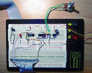
- MC68HC12B32 development board.
- DMM-01 Multimeter.
- HP5464D Digital Oscilloscope.
Software
- MCUez Assembler, linker, and debugger software.
- Ultraedit32 text editor.
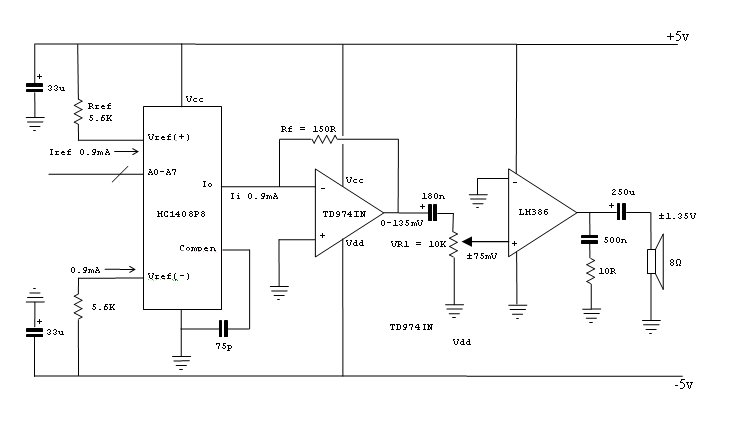
- 8-bit Digital-to-analog converter with amplifier to drive 8Ohm speaker The 8 bit sample output from the MCU needs to be converted to an analogue voltage. The first stage of this is achieved using the MC1408P8 DAC. The output from the DAC is a current varying from 0mA at all 0s input to ~0.9mA at all 1s input. The output current range is based off the reference current Iref at pin 14.
Iref = Vref / Rref
= 5V / 5.6KOhm
= 0.9mA
The output current Io from the DAC varies from 0 to Iref*255/256, by the equation:
Io = Iref * (A1/2 +A2/4 + A3/8 + A4/16 + A5/32 + A6/64 + A7/128 + A8/256)
The output from the DAC then enters the trans-impedance amplifier to be converted from a current range to a voltage range. The voltage range Vmax output being a linear function of the input current Ii and the feedback resistor Rf.
Rf = 150R
Ii = 0.9ma
Vmax = IR
= 0.0009* 150
= 135mV
The op-amp used for the trans-impedance amplifier is a TS974IN rail-to-rail op-amp, which was used to give a little more breathing room for easier development as the TL071 has a very small voltage swing when used with low voltages. The TL071 would have been fine in its place though just makes debugging slightly harder due to lower tolerances.
The output of the op-amp is then passed through a capacitor to filter DC and AC component around 50Hz and below from the signal and to condition it for the Amplifier which expects a ground referenced signal. The signal then enters a logarithmic pot configured as volume control VR1 into the LM386 setup as a 20 times gain amplifier. Giving a maximum peak to peak Vout of:
Vout = Vin * Gain
= 0.135 * 20
= 2.7V
There is also two 33uF capacitors on the negative and positive power supplys to filter out any feedback from the components. These made a significant difference feedback noise in the project.
- Jukebox user interface. A simple user interface was chosen with an introduction screen, a basic selection screen and an in play screen.
- Introduction screen. A simple screen that is displayed once on initialization of program.
- Selection screen. Allows for selection of a song.
- In play screen. Describes current state of system and allows canceling of song in progress.
- Primary sound buffer. All samples are rendered into a 64 word wrap around primary sound buffer located at 0x800. An 11KHz interrupt is setup (using output compare 7), to select the next sound sample from the buffer and place it on PORT-T.
- Midi decoder. Midi is a delta-time encoded event format. It comes in three formats Format 0, 1 and 2.
- Format 0 is a single track format where all midi channels are stored in one track.
- Format 1 is a multiple track format where each midi channel gets its own track and all tracks are played simultaneously based on track 0s delta time events.
- Format 2 is a multiple track format with multiple sequences (songs) each with their own delta time events.
- 12 channel sound renderer The midi specification requires a minimum of 16 channels of simultaneous samples to be played at once, typically in greater than 16 bit in greater than 44 KHz. Due to limitations of the MCU speed I limited this to 12 channels of 8 bit sound at 11 KHz. This roughly gave me:
- Sound Samples The midi samples were chosen to be basic sine waves due to lack of memory. The samples can be found in the file samples.asm. They are signed 8 bit 11 KHz samples.
- Sound Envelopes Typical midi samples have Attack Decay Sustain Release envelope which further modifies the sampled sound to be more like original instrument without using excessive amounts of memory. Due to limits of the MCU I chose to only implement a Sustain and Release for my sound samples.
- Sample frequency modification The samples are re-sampled at a new frequency based off a 8:8 fixed point lookup table basically generated from the equation
- Sample mixing
	Midi Juke Box
Press any key view selection
1-Courting 2-Ghosts'n'Goblins 3-Dixie
 4-Music Box Dancer 5-BubbleBobble
Playing song - press any key to stop
Interrupt initialization code:

	clr	OC7M
	clr	OC7D			; all timers disconnected from PORTT
	clr	TCTL1
	clr	TCTL2
	clr	TCTL3
	clr	TCTL4			; all timers disconnected from PORTT

	movb	#%10000000,TMSK1	; enable IOC channel 7 interrupt
	movb	#%10000000,TIOS		; enable IOC channel 7 to output

	movb	#%00001000, TMSK2 	;
	bset	TFLG1, #%10000000 	; reset interrupt tc07
	movb	#%11100000, TSCR 	; enable timer, fast flag clear
	movw	#sampleRate, TC7	; X Khz interrupt

	cli				; enable interrupts

The buffer has an insert pointer for new samples and a remove pointer for samples to play.  The insert pointer never passes the remove pointer.  If there are no samples to play the play code stalls until there is.

playNextSoundSample interrupt

	ldx	bufferRemovePtr
	cpx	bufferInsertPtr
	beq	playNextSoundSample_noSampleReady

	ldd	2,x+		; load next sample to play

	addd	#($7FFF-256)	; convert from 16bits signed to 8bits
	lsrd			; unsigned for output

	stab	PORTT		; store low byte of sample on PORT-T

	tfr	x,d		; make sure buffer doesn't exceed
	andb	#%1111111	; it's bounds
	std	bufferRemovePtr

playNextSoundSample_noSampleReady:
	bset	TFLG1, #%10000000	; reset interrupt  tc07
	rti
For the sake of simplicity I chose to decode format 0, also format 0 is the most common format.
The Midi specification required 16 channels of sound maximum to be played simultaneously during a tune. I limited this to 12 as the CPU would not manage 16.
Each sound channel has the following parameters:
| Parameter | Size(Bytes) | Description |
| state | 1 | 0 available, 1 playing, 2 decaying |
| midiChannel | 1 | Current midi channel assigned to this sample channel. |
| note | 1 | Note being played. |
| envVolume | 2 | Current envelope volume. |
| envDelta | 2 | Delta for envelope per sample. |
| samplePtr | 2 | Current pointer to sample being played. |
| sampleLoopStart | 2 | Pointer to beginning of sample. |
| sampleLoopEnd | 2 | Pointer to end of sample. |
| sampleSubPos | 2 | Used to play sample at varying speeds. |
| sampleSubPosAdd | 2 | Rate to play sample at. 256 = 1:1 |
| sampleLoopStartEndDiff | 2 | Difference between sample loop start and end. |
The basic midi rendering loops is as follows.
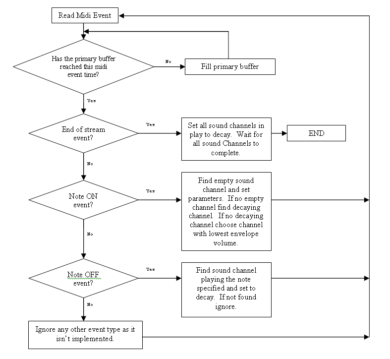
The fill buffer loop basically works out how much of the buffer is empty and then calls the sound renderer to render the empty buffer space.
	CPU Cycles per channel per Hz  	= CPU MHz / channels / sample rate
					= 8 MHz / 12 / 11 KHz
					= 60 cycles
Some quick pseudo-code showed that this was feasible.
The sound render renders 12 channels maximum to the primary sound buffer.
It consists of the following parts:
Sustain is required to differentiate between multiple notes played in sequence with the same note. And the decay is added to prevent notes from clipping when they are turned off.
n = number of semitones above the base sample you want to resample to.
Step = 2n/12
e.g. If we have a note at 440Hz that we wanted to resample up 2 semitones:
		step 	= 2n/12
			= 1.1225(4sf)
	440 Hz x step 	= 493.9 Hz
There is no antialiasing in the resampling which causes some erroneous noise to be present in the output. But no more CPU cycles are available to implement resampling.
An 8:8 fixed point value is allows for stepping through the sample at anywhere from 1/256th speed to 256 times speed.
The basic sound rendering loop:
	; // envelopeVolume -= envelopeDecay;
	ldd	chan_envelopeVolume
	subd	chan_envelopeDelta
	bmi	ENDSAMPLE		; if envelope reachs 0 then the sample
	std	chan_envelopeVolume	; is dead
	tfr	d,y			; save envelope volume in y

	; // sampleSubPos += sampleSubPosAdd; sampleSub pos is in 8:8 fixed point
	ldd	chan_sampleSubPos	; update pointer to current sample index
	addd	chan_sampleSubPosAdd; just storing the low byte effectively
	stab	chan_sampleSubPos+1	; rounds the high byte off

	; // v = samplePos+(int)SampleSubPos
	ldx	chan_samplePtr	; increment the real sample position
	ldab	x			; by the whole amount of the sampleSubPos
	leax	a,x			; and load the new sample

	cpx	chan_sampleLoopEnd	;
	bge	RESET_SAMPLEPTR	; have we reached the end of the loop?

BACK_FROM_RESET_SAMPLE_PTR:
	stx	chan\1_samplePtr	; if so reset to start of loop

	; // [bufferInsertPos++] = v * envelopeVolume;
	sex	b,d			; convert 8bit signed sample to 16bit signed
	emuls				; sample
	tfr	y,d			; scale sample to envlope
	addd	SP			; add sample to other channels samples
	std	SP			; and store

	bra SKIP			;

RESET_SAMPLEPTR:
	exg	d,x			;
	subd	chan\1_sampleLoopStartEndDiff	;
	exg	d,x			;
	bra	BACK_FROM_RESET_SAMPLE_PTR

ENDSAMPLE:
	clr	chan\1_state

SKIP:
All 12 channels are mixed together with simple addition. This has the benefit of no loss in quality initially from the mixing, but requires a final stage to convert the 16 bit sample to a more manageable quantity i.e. 8 bits.
At least 95% of the development was done using the HC12 simulator which was a little tough as it lacked certain peripherals the development system, and would only log changes to certain ports requiring slightly different code in the lab versus in home. I actually asked the author of HC12 Simulator if he would let me improve his simulator to match our setup but he declined.
Sound quality is good, but there is some noise generated from the following areas:
- 16 bit to 8 bit conversion for output This was to be expected and cannot be helped without a wider DAC.
- Software volume modification i.e. the envelopes. This cannot be helped without moving to higher precision internally in the MCU, which is not an option unless there was a significant drop in channels and sample rate. It is an extremely minor effect and can be ignored.
- Hardware noise. There is very little noise detectable on a scope in the hardware and undetectable to me in listening tests. Some noise comes from the digital interface to the MCU but this doesn't make it through to the LM386 output in any significant quantity. I'd also expect some thermal noise to be present, but in even less quantity than the digital noise. It could be easily filtered out with a capacitor if it were appreciable.
This is the main cause of noise in the system.
The development system unfortunately runs off external memory which meant I had almost half the CPU cycles to use in the end. If I had written the program to flash I would have been able to use a 22 KHz sound renderer.
Examples of Midi sequences extracted from the simulator can be found at http://www.giantfriend.com/midiProject/
http://crystal.apana.org.au/ghansper/midi_introduction/contents.html
http://www.borg.com/~jglatt/tech/midifile.htm
http://www.csw2.co.uk/tech/midi2.htm